
Many people have asked about the new ignition system we installed and like the novelty of the voice addition. We will cover the details here with a parts list to help guide your project.
Viatori Keyless Ignitions
Solving the Riddle
When we first took ownership of the Viatori we ran into an ignition issue on the starboard engine, the engine wouldn't turn over. We quickly diagnosed the issue to be a faulty ignition switch and ordered 2 in the event this was going to be an issue with the port engine as well. Over the years the ignition on the starboard side would burn out and we would have to replace it. At just over $400 an ignition switch, it was becoming a very expensive annoyance. In April of 2025, the ignition failed again but this time, switching to a spare ignition did nothing. We got the engine started by jumping the starting relay with a small screw driver, a less than ideal situation.
Once we settled into a marina for the summer, we dove into the issue and traced a two main problems. The first issue was that at some point before we owned the vessel, someone had worked on the ignition and wired the ignition wrong. The low voltage wire from the alternator that should have gone to the alarm panel was connected to the start switch of the ignition. Over time, this continual voltage from on the momentary switch wore it out. The second issue was that this continual voltage to start switch also kept power to the neutral safety switch, and over time this failed as well. Unfortunately, the neutral safety switch on the throttle system we have is embedded on the control board of 20 year old out of production equipment with no way to repair.
We had to start the engine and we couldn't keep jumping the relay every time either. So we came up with a plan to give us some added security and get rid of the big bulky keys.
The Solution
We located a company, JDI, that made keyless ignition systems for cars and trucks. They also make a unit called Ghost Power that uses an RFID chip to turn power on and off. Our engines, Volvo TAMD63P, use a fuel solenoid to stop the fuel flow and shut the engine down. This requires a 12v current to activate. Once the engine is stopped, the solenoid goes back to the open position so the engine can be started. The stop and start function of the ignition uses momentary switches, only powered while the switch is depressed. A momentary switch is spring loaded and once released, returns to the off position. The power to the accessories, gauges, lights, and other items, is a locked switch, meaning once the switch is activated, power continually flows until it is put in the off position. Using the JDI Ghost Power coupled with switches from New Wire, we could install a system to meet our needs and be connected to new control hardware neutral safety switch in the future.
The Nitty Gritty
The first this was to layout how the system was going to work and what the starting procedures were going to be. This ensured we not missing any details. The Ghost Power is connected to the starting batteries for main power. There are two switched powers wires at 30 amps, a switched ground wire and sensor wire that keeps the unit powered while current is flowing to the device. The installation is fairly simple, but of course we had to make it more complicated.
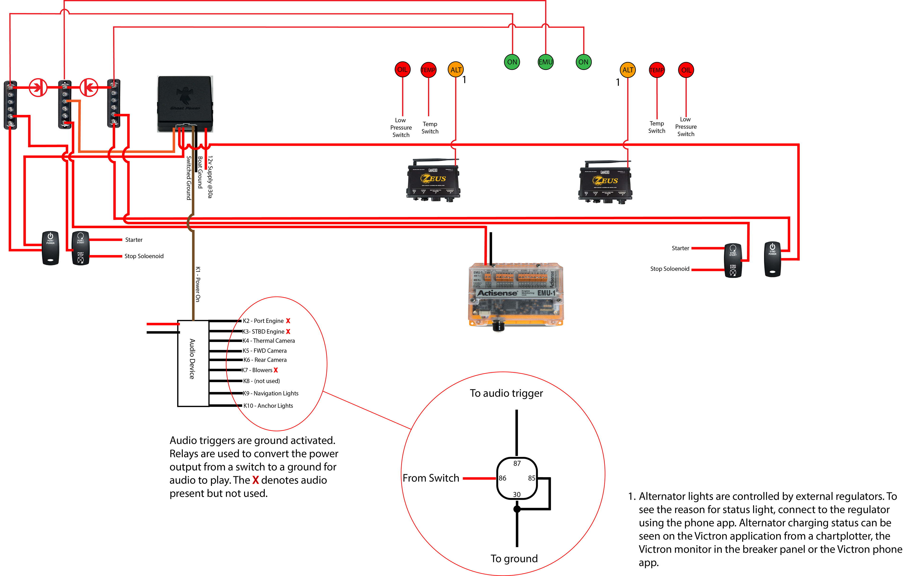
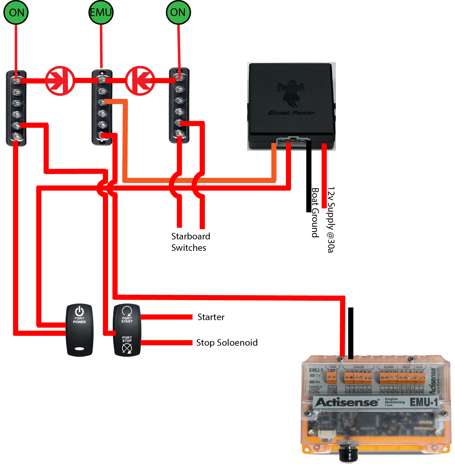
Once the system is turned on, you have 45 seconds to activate the power switch or the power will shut off automatically. This feature also works once the power switch is shut off, the system will lock out and you will need the RFID key to re-activate. When the power is turned on, the power switches can be activated. This gives power to the accessories. These are the oil pressure senders, oil switch, temperature sender, the EMU, regulators and other devices that are normally powered by the accessory position of the keyed ignition. A power indicator lamp comes on letting you know that the power is activated. At the same time the EMU light will come on letting you know the unit has power. The flow of electricity is controlled by inline diodes so that when you turn on the port side power, the starboard is not powered until that switch is activated. The EMU converts analog pulses into signals onto the NMEA2000 network.
To change from the standard alarm panel only requires a basic understanding of switches, at least on the older engines that do not use more advanced ECU's. An oil pressure or temperature switch allows current to flow when the mechanical device is triggered, completing a circuit. When an oil pressure switch has no pressure, the engine is stopped, the circuit is complete, the alarm buzzer sounds and a light comes on. When the engine starts pressure rises and the switch is open turning the light off.
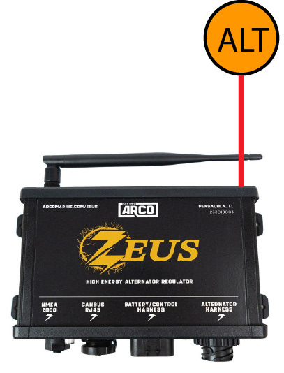
In most common situations, the alarm panel has a battery light that will come on. This come one when there is low voltage at the battery, low output from the alternator, high temperatures at the alternators, over charging or excessive voltage from the battery. This is normally just a red light and you are left trying to figure out what it means. With our system, the alternator light will now flash a code to tell you what is wrong. You can check this by logging into the alternator app or checking the alternator status on the chart plotter. Coupled with the Victron GX you can see status of each battery and the alternator output.
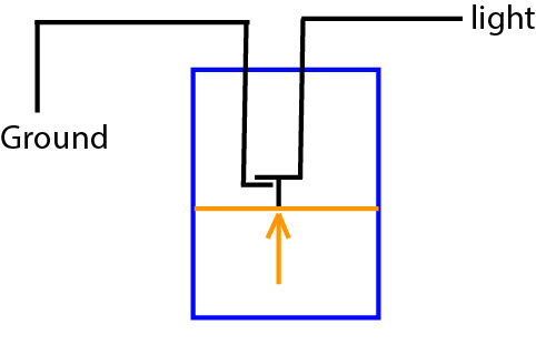
To make our system more complicated, we added voice alerts to certain functions, turning the power on, turning on nav and anchor lights and turning on the cameras. To do this we ElevenLabs text to voice service, free, to have the system say what we wanted. We downloaded our audio files to a an audio playback device. The device uses negative (ground) triggers to play the audio. This was fine for the initial start up as the JDI Ghost Power has a switched ground. The other audio is triggered using relays to convert the power output to the device to a ground signal for the audio.
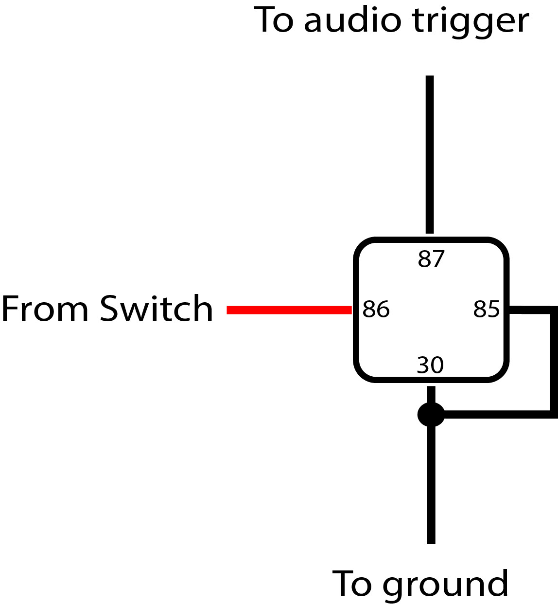
Basic relays consist of four pins. Pin 30 is the input, pin 86 is the trigger voltage to activate the relay, pin 85 is the ground, and pin 87 is the output to the device. Normally pin 30 would be 12v supply, but since we need convert this for the audio to work, you connect a common ground to this pin instead. You can jump pin 30 and 85 together, and connect pin 87 to the audio trigger you want. The device power switch, power going to the device, is split and connected to the device and to pin 86. When pin 86 gets power from turning on the device, the relay now becomes a ground output and the audio is triggered.

The speakers we used are 2-inch-4ohm-5w.
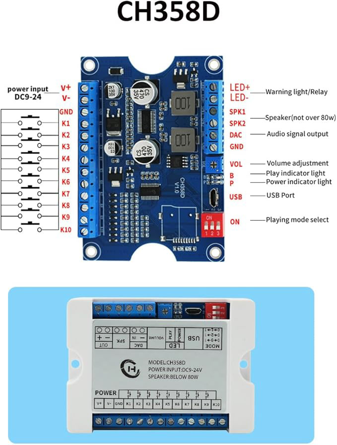
The audio playback device we used is the Playback Module CH358D.
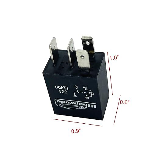
For the triggers we used 4 Pin Micro Relays.
For the audio we used a free Text to Speech service, ElevenLabs.